
Vertical connection
Building Risers & Floor Distribution
Coordinate the incoming cable, floor take-offs and protected termination points with available riser space and access.
Follow the building route →From the campus backbone to the last patch-panel port, bring routes, components and room for change into focus. BAGYOU FIBRE connects the physical details behind a workable optical network.
Select each part for the job it performs, then check the connections between them.
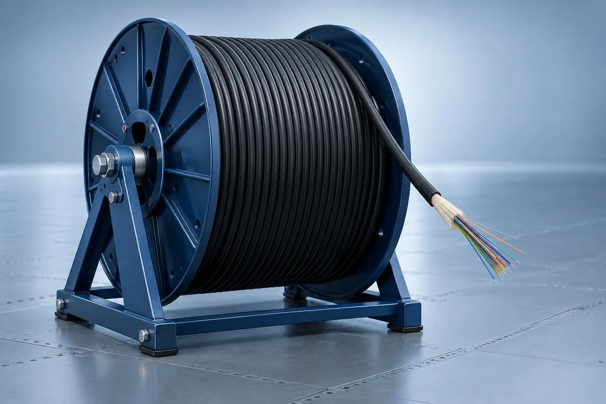
Construction, core count and route conditions.
View cable options →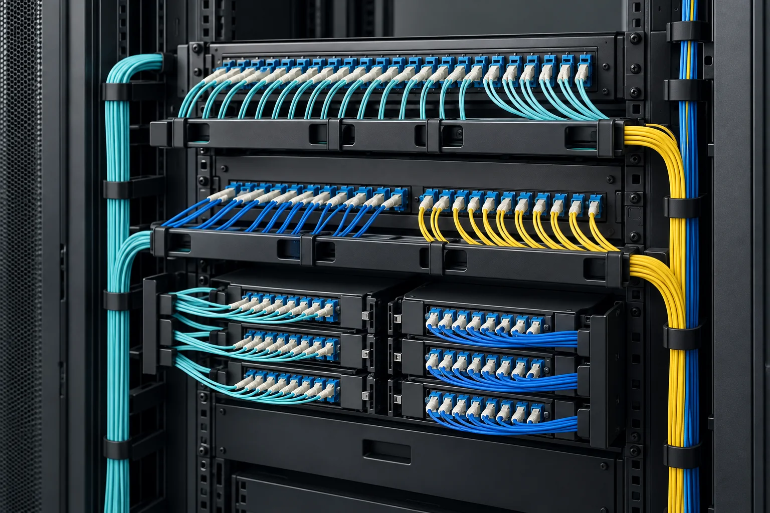
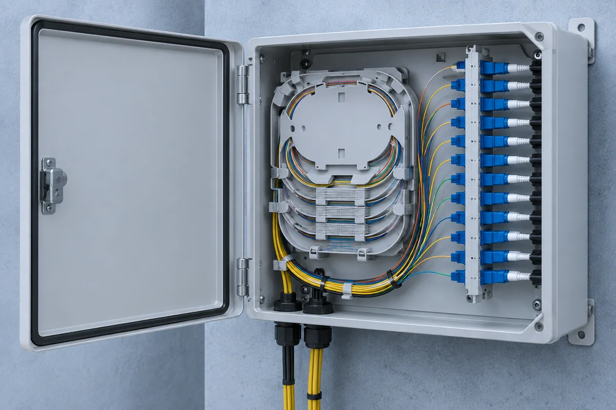
Accessible fiber storage and defined port capacity.
View termination options →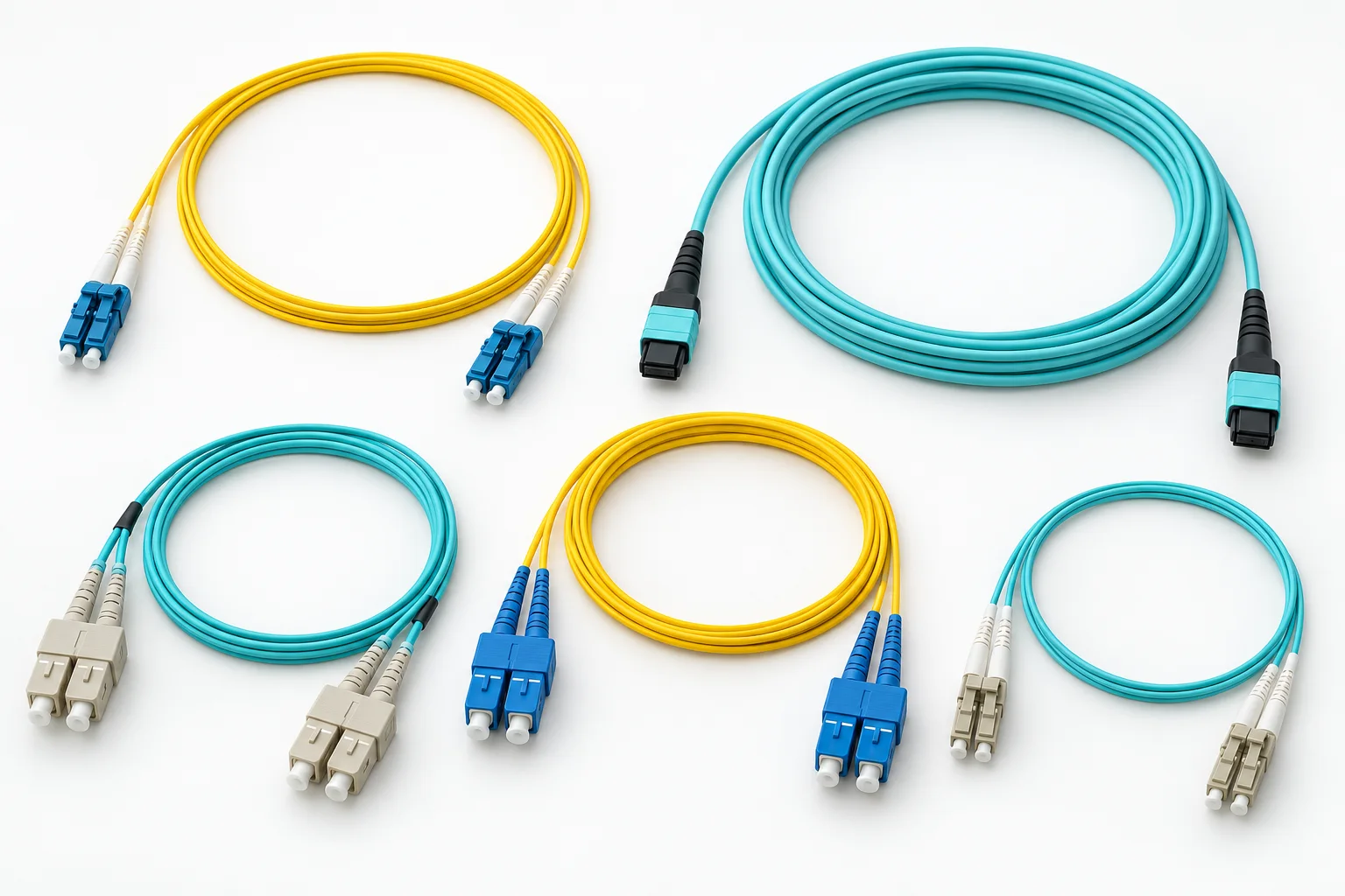
Connector interfaces, polarity and service reach.
View patching options →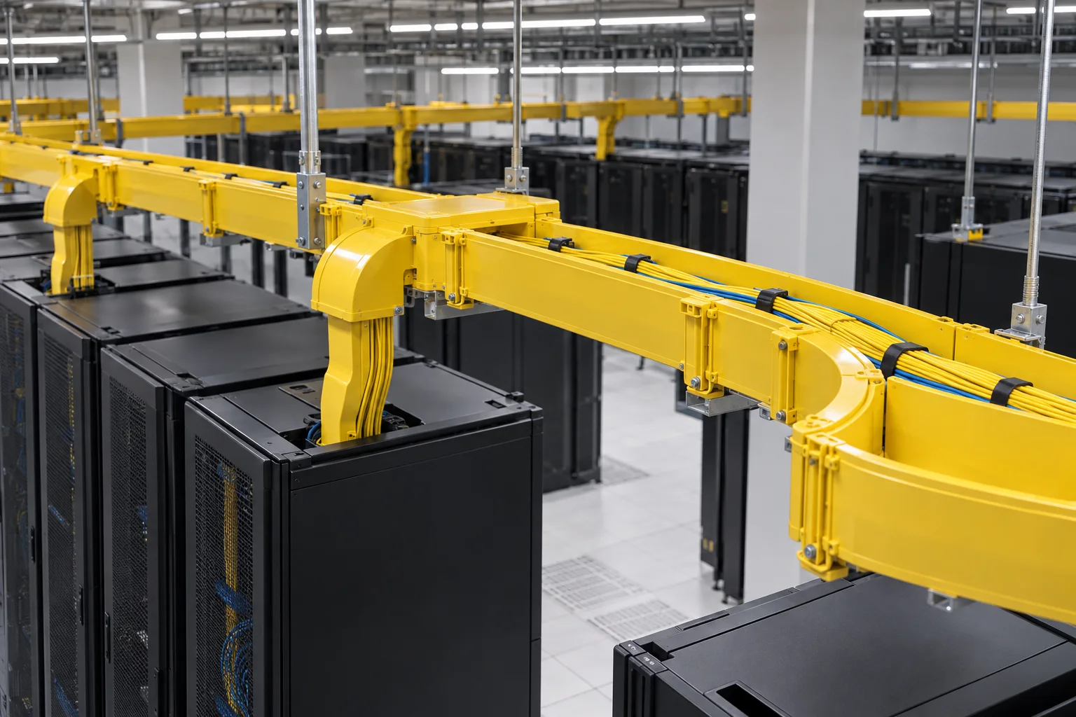
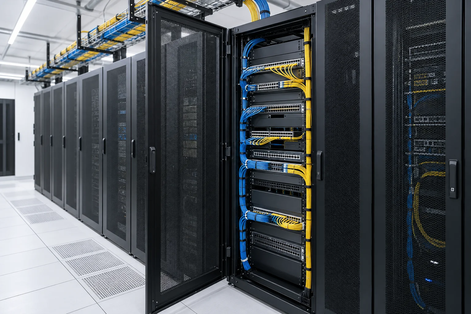
Bend control, usable space and maintenance access.
View pathway options →Coordinate the incoming cable, floor take-offs and protected termination points with available riser space and access.
Follow the building route →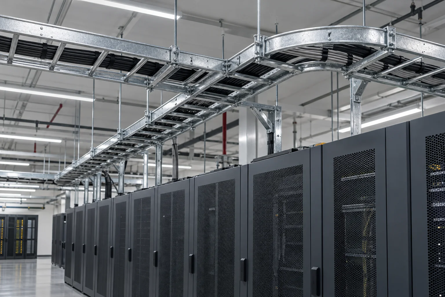
Record route lengths, building entry points, fiber capacity and spare pathways before planning the next connection.
Connect the campus plan →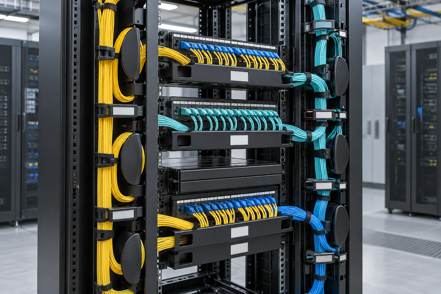
Plan panel space, connector compatibility, patch-cord reach and a controlled changeover that can be documented.
Review the patching layout →Four short records help connect the design intention to the installed network.
Show the buildings, floors, pathways, entries and approximate cable lengths.
Count working and spare fibers, panel ports, rack space and intended growth.
Identify retained links, new connections, temporary patching and service windows.
Agree labels, patching records and tests before the installation is closed out.
Explore the optical terminology and field details behind component selection and network planning.
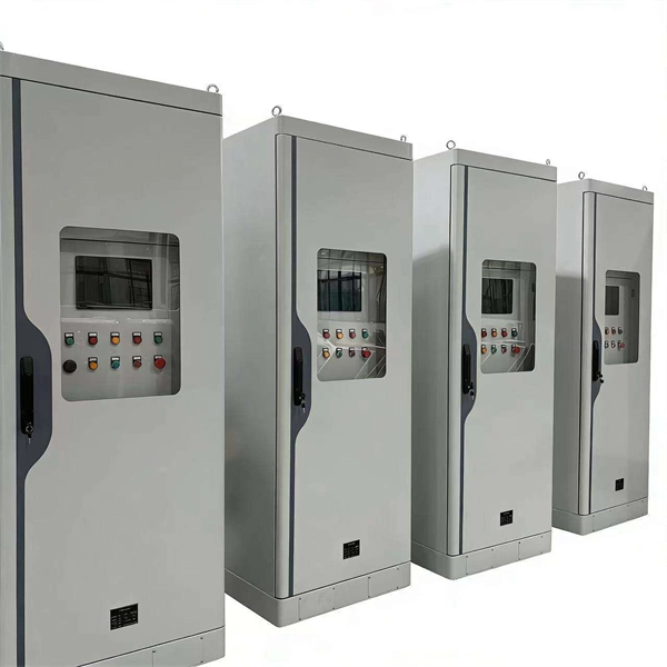
These Emergency Power off Panels enable rapid power shutoff that minimizes further injury and damage to personnel and equipment, respectively. These ePDUs are hardwired and the power off switch can be housed anywhere…
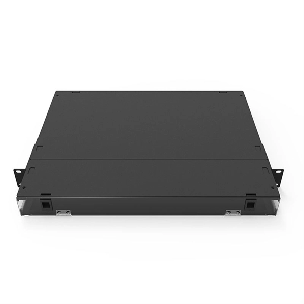
Optical Distribution Frames/Patch PanelODFs often come with pre-installed cable entries, splice trays, pigtails, and adapters. However, it is also possible.
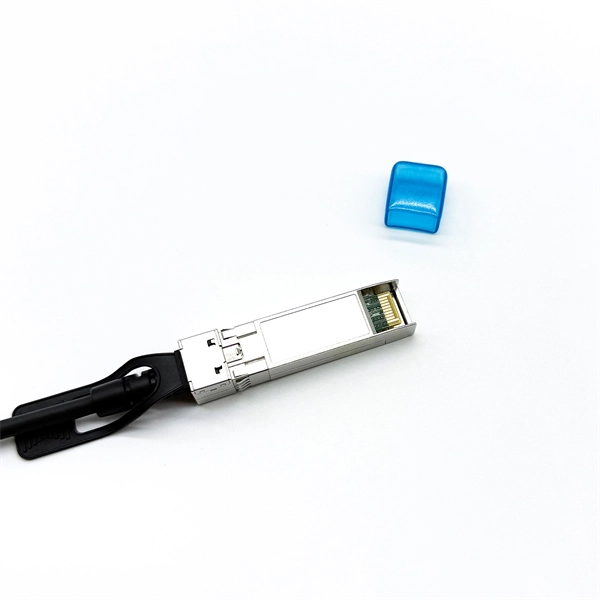
HDMI Single-Mode Fiber Converters allows the transport of 12G-SDI or 3G-SDI over distances up to 10km when using standard Single-Mode fiber optic cable with LC connectors. HDMI 12G LC models support video formats all…
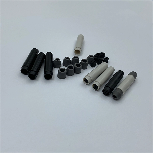
How To Find Buried Fiber Optic Cable? Locating buried fiber optic cables is a critical task that requires precision and care. By using the right tools and.
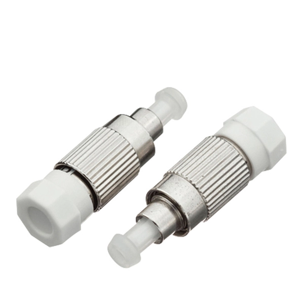
Ultra-weak fiber Bragg grating (UWFBG) arrays can significantly enhance backscattering intensity and thereby improve DAS performance. This is achieved by creating a periodic variation in the refractive index of the fi…
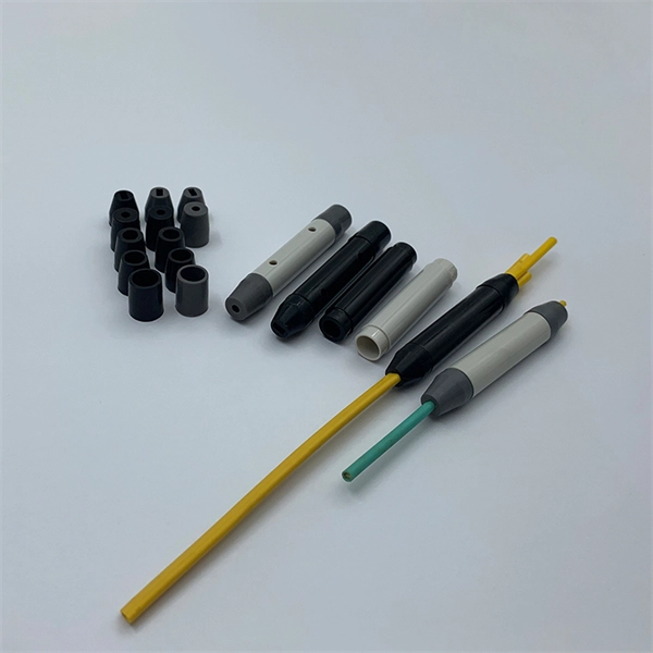
Fiber Optic Sensors vs Proximity Sensors: Key Differences and Explore the fundamental differences between fiber optic sensors and proximity sensors. This g.
Useful answers begin with an accurate record of the route and what is already installed.
Identify the equipment rooms, floors and tenant or service areas that need connections. Record the available risers and pathways, approximate distances, active interfaces and the capacity reserved for later use before choosing cable and termination products.
Start with a record of installed fiber, routes, connectors and test results. Separate components that can remain from those that need replacement, then define temporary patching, service interruptions and acceptance checks for each stage. Existing compatibility must be verified rather than assumed.
Spare fibers are unused cores within an installed cable. Spare panel capacity is the available space or ports for termination and patching. Both affect expansion, but neither automatically guarantees enough pathway capacity, compatible interfaces or optical performance.
Compare the same cable construction and length, fiber count, termination method, connector and polish, panel accessories, patch-cord quantities and test scope. Include installation and handover work so that component prices can be considered alongside the complete project cost.
Retain route and cable schedules, panel and port labels, splice or termination records, patching arrangements and the agreed test results. Mark spare capacity and any unresolved conditions so that maintenance teams can understand the installed link.
The regional project coordination location is Las Tablas, Fuencarral El Pardo, Madrid, Spain. Contact BAGYOU FIBRE by email or WhatsApp to discuss project details and confirm any meeting arrangements directly.
Share a building drawing, campus route, panel schedule or upgrade outline, including the questions that still need an answer.
Regional project coordination · Las Tablas, Fuencarral El Pardo, Madrid, Spain